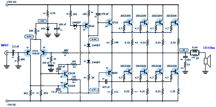
This is the schematic design of 400 Watt 70 Volt amplifier capable to deliver about 400W RMS power output in single channel. The component part list, PCB layout design and component placement layout is provided in this post. The power supply module already included ini the PCB design. The components are easily found in market. This circuit is using 8 transistors of 2SC5200 mounted in PCB, the heatsink is required and should be mounted in the power transistors to prevent overheat and maintain the amplifier’s good performance.
400 Watt 70 Volt Amplifier Part List
Transistors
- 2SC5200 or equivalent MJL21194 : 8
- 2SD718 or equivalent C5198 : 1
- 2SB688 or equivalent A1941 : 1
- 2SC2229 or 2SC2230 : 2
- A1015 or A872 : 2
- TIP42 : 1
Capacitors
- 6800uF/80V or 10000uF/80V Electrolytic Capacitor : 2
- 100uF/80V Electrolytic Capacitor : 2
- 2.2uF/50V Electrolytic Capacitor : 1
- 10pF ceramic capacitor : 2
- 470pF (471) ceramic capacitor : 2
Resistors
- 0.33 ohm 5W : 8
- 4.7 ohm 1W : 8
- 100 ohm 1W resistors (brown, black, brown) : 2
- 33 ohm 1/4W (orange, orange, black) : 1
- 150 ohm resistors at 1/4W (brown, green, brown) : 3
- 10K ohm 1/4W Resistor (Brown, Black, Orange) : 1
- 1K ohm 1/4W Resistor (Brown, Black, Purple) : 1
- 4.7K ohm 1W (yellow, violet, purple) : 1
- 68K ohm 1/4W (blue, green, orange) : 2
- 33K ohm to 1/4W (orange, orange, orange) : 1
- 3.3K ohm 1/4W resistors (orange, white, purple) : 2
Diodes
- Diode bridge of 15 amps or greater : 1
- Diodes 1N4007 : 3
- Zener Diode of 18 volts or 24 volts : 1
Others
- Fuse holder and fuse of 3 amperes.
- Transformer for the amplifier should be 55 + 55 volts AC with a current of at least 10 amps.
400 Watt 70 Volt Amplifier PCB Layout Design
This is the PCB layout for 400w pawer audio amplifier. The power supply is already included in the printed circuit board although in the schematic design, the power supply was not included. Please refer to the connection image in the end of this post.

400 Watt 70 Volt Amplifier Top PCB Design and Component Layout


400W Power Amplifier Connection


Good day..do you have a preamp for the 400watts 70 volts amplifier..thank in advance
This circuit is working?
Hello sir, I need PCB layouts
Hi, can you send me the pcb in format .pdf on email royalpcb@yahoo.com
Thanks
minimal use transformer how Amper
I buy in PCB
Besides, in laying out PCB components of LED switching power supply, it is suggested that engineers should arrange the position of every functional circuit based on the procedure of the circuits. This kind of layout will will the signal flow more effectively and rapidly and make the signals maintain the same direction. In laying out PCB board, the first principle is to ensure routing rate; connection between the flying lines should also be paid special attention; components connected with wires should be put together. The size of loop should be reduced to the minimum extend to stop radiated disturbance of the switching power.
Howmany watts impedance
This circuit 400 Watt 70 Volt Amplifier is not working, distorted sound heard at the speaker.
Its smart and useful
s’il vous plais j’aimerais demander si c’est les 2 circuits qui sont 400W ou bien un seul. merci
thanx for the circuit.it is working well.I am asking for the same circuit that uses only npn transistors(2sc5200) but with a higher input voltage