Transistors T1 and T2 makes a first differential stage, current source of +/- 1 mA is set by R3. P1 allows a fine tuning of DC voltage at amplifier’s output. Place P1 at it’s half value for first power up, then turn it slowly for a lowest DC output voltage. It is recommended to use a first quality component.
Input sensitivity is 1.2 volts. The gain of 27x is archived by R7/R6. It may be modified by changing R7 value. Transistors T5 and T6 makes the second differential stage. Transistors T3 and T4 works as a current mirror source. They push the second differential stage to drain equal current. Doing so we get a high gain and an excellent linearity. Output MOSFET transistors works in AB class, their quiescient current is set from 50 to 100 mA trough P2. For setting quiescient current, you must set P2 in minimal resistance, place a multimeter in mV DC range accross on R14 or R15 leads, turn slowly the screw untill you read a 16,5 mV value, which correspond to a 50 mA quiescient current. F1 and F2 works as an elementary output short-circuit protection.
Note :
Before connecting a speaker at amplifier output, connect a multimeter at output and look on DC output voltage. This level never may be greater than 50 mV. If it is so, check all amplifier for a mistake. Also, change T2 with another device and check again.
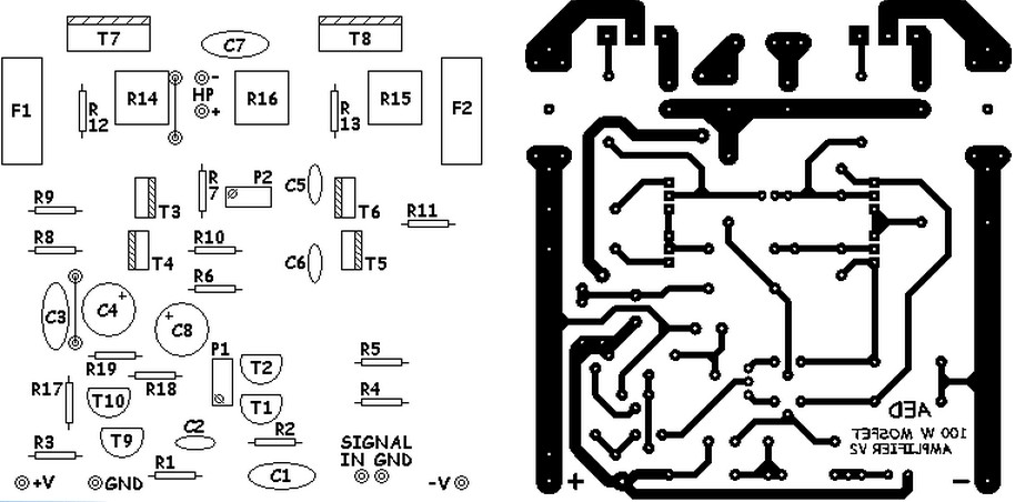
Parts list :
C1 = 2.2 uF MKP, MKT 100 V
C2 = 330 pF ceramic 50 V
C3 = 100 nF MKP, MKT 100 V
C4 = 40 uF 100 V electro-chemical
C5, C6 = 18 pF ceramic 50 V
C7 = 100 nF MKP, MKT 250 V
C8 = 47 uF 100 V)
R1 = 47 K
R 3 = 470 Ohms
R2 = 2K2
R4, R5 = 3K9
R6 = 1 K
R7 = 27 K
R8, R9, R11 = 100 ohms
R10 = 10 K
R12, R13 = 470 ohms
R14, R15 = 0.33 ohm 5 watts
R16 = 10 ohm 3 watt
R17 = 1 K
R18, R19 = 10K
T1, T2, T9, T10 = 2N5401, ZTX558, BC556B (note the different pinout - take care for pin layout)
T3, T4 = BF470, MJE350, 2SB649
T5, T6 = BF469, MJE340, 2SD669
T7 = IRFP240, 2SK1530, 2SJ162, BUZ900DP, BUZ901DP (note the different pinout - take care for pin layout: GDS GSD)
T8 = IRFP9240, 2SJ201, 2SK1058, BUZ905DP, BUZ906DP (note the different pinout - take care for pin layout: GDS GSD)
P1 = 100 ohms (25 laps - 25 turns)
P2 = 2K5 (25 laps - 25 turns)
F1, F2 = 3 T A
Class-D Power Audio Amplifier Using MD7120 MOSFET Driver This is the circuit design of Class-D…
This is the circuit diagram of active antenna amplifier for FM radio device. With only…
This is the schematic design of 400 Watt 70 Volt amplifier capable to deliver about…
This is the circuit diagram of 150W power amplifier which built using power transistors. The…
This is the circuit design of 1000W stereo audio amplifier. It is a very good…
This is the circuit design of 150W car audio amplifier. The circuit is divided in…
View Comments
waoh good out put...
T7 indicated in the circuit diagram is 2SJ 162 and T8 is 2SK 1058. Is this correct or should be reversed?