
This is the circuit diagram of 40W power amplifier which built based on power transistor TIP33C and TIP34C as the main part here. It works with symmetrical / dual power supply. The heatsink must be used to prevent overheating to the transistors.
Parts List:
| Resistors: 0,47 ohm 5 Watt : 2 10 ohm 2W : 1 33 ohm 2W : 1 100 ohm 2W : 2 10K ohm 2W : 1 5,6 ohm (1/4 Watt) : 2 120 ohm : 5 220 ohm : 1 470 ohm : 1 1K ohm : 2 4K7 ohm : 1 6K8 ohm : 1 15K ohm : 2 |
Capacitors: 220uF / 35V : 1 100uF / 50V : 2 10uF / 25V : 2 0,1uF / 100V Poliester :2 180 pF : 1 100 pF : 1 |
Others: TIP33C : 1 TIP34C : 1 BD139 : 3 BD140 : 2 BC558 : 3 BC548 : 3 1N4007 : 6 LED Red : 1 Preset 500 ohm |
In this amplifier use a system called “differential amplifier current mirror”, we see to the right of this, which is far superior in performance. It consists of a constant current generator Q1, which provides a current of about 4mA that feeds the differential pair Q2 and Q3, which are forced to work in symmetry by transistors Q4 and Q5, as we see, having the bases connected together , force a branch to repeat the flow from the other. Moreover, the load (RL) connected to this differential is much lighter, because rather than going to the base of a single driver, which has a low impedance, is connected to a driver comprising two transistors, making the impedance rises and more “light” work to excite the current amplifier. As a result we get more “freedom” in sound, clarity, greater slew rate and a very low intermodulation distortion.
The current amplifier comprises two complementary pairs Darlington, armed around the BD139 and BD140 + + TIP33C TIP34C known, I have been given ample proof of strength and loyalty. To stabilize the quiescent current of the output transistors I use the simple but effective method of anchoring the base bias using 4 diodes 1N4007. Note that the diodes are on the edge of the sink output, that is to have thermal contact with it, because if heated output stage voltage decreases joint, doing the same quiescent current. It is fixed by means of preset about 500 ohms at 10mA, measured by placing a scale tester with a 200 millivolt peak in the speaker output and the other at one end of one of the emitter resistors 0,47 ohm 5 Watt. You should turn the preset to have a reading of 5 mV or so.
40W Power Amplifier PCB Layout:
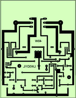
Layout for component placement:


